Flow defines (in very flexible ways) a spatial geometry and set of geometric
objects that represent spatial elements of hydrologic system (see figure below). Terrestrial elements
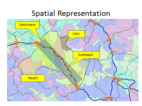
are organized as Hydrologic Response Units (HRUs) that are represented by collections of polygons in a
source layer (typically the IDU layer) with common attributes. HRUs are a fundamental unit of terrestrial
hydrologic representation in Flow. They can consist of one or more layers (HRUPool objects) that maintain
water content information and any number of additional state variables (e.g. heat, nitrogen level.)
HRU Layers
come in three flavors: snow, vegetation, and soil; any number (including zero) of any of these layer types can be
defined, but they are always sequenced top to bottom with snow on top, vegetation in the middle and soil layers
on the bottom. HRUs are collected into catchments (Catchment objects) with a single drainage point. These are assembled
by Flow from a GIS layer (MapLayer object) managed by Envision, typically the IDU layer, that has relevant spatial data
used to define or model the hydrologic system.
Similarly, the stream/river network is represented by a
linear feature network coverage (MapLayer object), also managed by Envision, that represents the river
system network layer that resides “on top” of the IDU coverage. Reaches are subdivided into “subnodes”
that can be spaced as needed for a particular model construct. Catchments, HRUs and Reaches are defined
by “spatial aggregates”, collections of polygons that have similar attributes. HRUPools always nest within
an HRU and HRU’s always nest in a catchment. The spatial domain of these aggregates can be limited, meaning
a subset of base layer terrestrial polygons or stream layer lines can by selected into the aggregates; any
excluded polygons/lines are simply ignored by the model.
State variable information is maintained at the HRUPool level and at the Reach subnode level. By default,
a single state variable related to water content is maintained by these containers. Additional state
variables, representing transported constituents, can be easily added by specifying them in the input Xml file.
Topologically, Flow defines and manages hydrological connectivity between Catchments and Reaches – catchments “know”
what reach they are connected to, and vice versa. Flow assumes that terrestrial/riverine connectivity is between
catchments and reaches only; i.e. all lateral inflow/outflow from a catchment’s HRUPools is collected at the catchment
level and transferred to the reach corresponding to a catchment. Connectivity is defined through a join column that must
be present in the catchment coverage, with a related join column in the reach coverage; catchments are joined to reaches
that share common values in their join fields; this is assumed to be a 1:1 relationship; one catchment can be associated
with no more than one reach, and one reach can be associated with no more than one catchment.